Heated Circuit Complete Guide

Warm Inspired Air Control Unit Manuals / Instructions
Trouble Shooting Error Messages
Messages Displayed By the Warm Inspired Air Control Unit
Error 0 (displayed “Err0”) and Error 4 (displayed “Err4”)
When all cables and connectors are attached correctly and in good working order, the digital readout window of the Warm Inspired Air Control Unit displays temperatures. However, if there is a problem with the Auxiliary Temperature Probe (part #8617 or #8618) or the Heated SW Circuit (part #8347 or #8348) or the the control unit itself, you can see two possible error messages
- Error “0” means no cables are connected to the unit or the heating circuit in the Warm Inspired Air Control Unit and the sensor circuit in the Heated SW Circuit are both faulty.
- Error “4” means that the sensor circuit in the Heated SW Circuit is faulty, but the heating circuit itself inside the Warm Inspired Air Control Unit is OK
The following tests identify the most common sources of the error messages, since they test the Auxiliary Temperature Probe and the Heated SW Circuit separately. In the unlikely event that a fault would appear suddenly in both, further testing is required. Contact DarvallVet Technical Support at 866-931-3292 X102.
Test Process:
- Error “0” – Turn the unit off and disconnect the Auxiliary Temperature Probe and the Heated SW Circuit connecting cable (part #8615). Turn the unit on. The unit should display the Error Message “0” (Err0). This is normal. It indicates that no cables are connected to the unit.
- Turn the unit off and connect the Auxiliary Temperature Probe. Turn the unit on. The unit should no longer display the Error Message “0” (Err0). If the error message persists, it indicates:
- The Auxiliary Temperature Probe is faulty
- Connect a different Auxiliary Temperature Probe to the unit. If the unit no longer displays the error message, the problem has been identified as a faulty Auxiliary Temperature Probe. Discard the damaged Auxiliary Temperature Probe. If the error message persists:
- There is a fault within the Warm Inspired Air Control Unit
- Contact DarvallVet Technical Support at 866-931-3292 X102.
- The Auxiliary Temperature Probe is faulty
- Error “4” – Turn the unit off, disconnect the Auxiliary Temperature Probe and connect the Heated SW Circuit connecting cable (part #8615). Ensure the 15-pin connector is securely fitted. Connect the 4-pin end of the Heated SW Circuit connecting cable to a Heated SW Circuit. Turn the unit on. The unit should no longer display the Error Message “4” (Err4). If the error message persists, it indicates:
- The 15-pin connector is not attached securely. If the 15-pin connector is not fitted correctly it can cause an Error “0” (Err0) or Error “4” (Err4) message.
- Turn the unit off. Reattach the 15-pin connector securely. Turn on the unit. If the unit no longer displays the error message, the problem has been identified. Always attach the 15-pin connector properly in the future. If the error message persists:
- The Heated SW Circuit is faulty.
- Connect a different Heated SW Circuit to the cable. If the unit no longer displays the error message, the problem has been identified as a faulty Heated SW Circuit. Discard the damaged Heated SW breathing circuit. If the error message persists: If the error message persists, contact DarvallVet Technical Support at 866-931-3292 X102.
- The 15-pin connector is not attached securely. If the 15-pin connector is not fitted correctly it can cause an Error “0” (Err0) or Error “4” (Err4) message.
Using Smooth Wall Heated Breathing Circuits
Caution - Avoid Direct Skin Contact
Darvall Heated SW Breathing Circuit tubing is NOT designed for surface warming of skin.
Avoid prolonged direct contact with the animal’s skin.
DO NOT position heated tubing under anesthetized animal’s body or limbs at any time.
If skin contact is unavoidable due to patient positioning
- Always protect the animal’s skin from the heated tubing with a barrier such as a dry cloth towel positioned between the animal and the tubing.
- Always keep the heated tubing uncovered and above or to the side of the animal.
- DO NOT position heated tubing underneath an animal’s body or limbs.
- DO NOT cover or wrap the heated tubing.
Covering the heated tubing with the animal’s body or limbs, covering it with a sandbag or wrapping a section of heated tubing with a towel can concentrate heat in one area of the tubing. This concentration of heat can raise the tubing wall temperature high enough to burn skin.
Heated SW Circuit Connectors
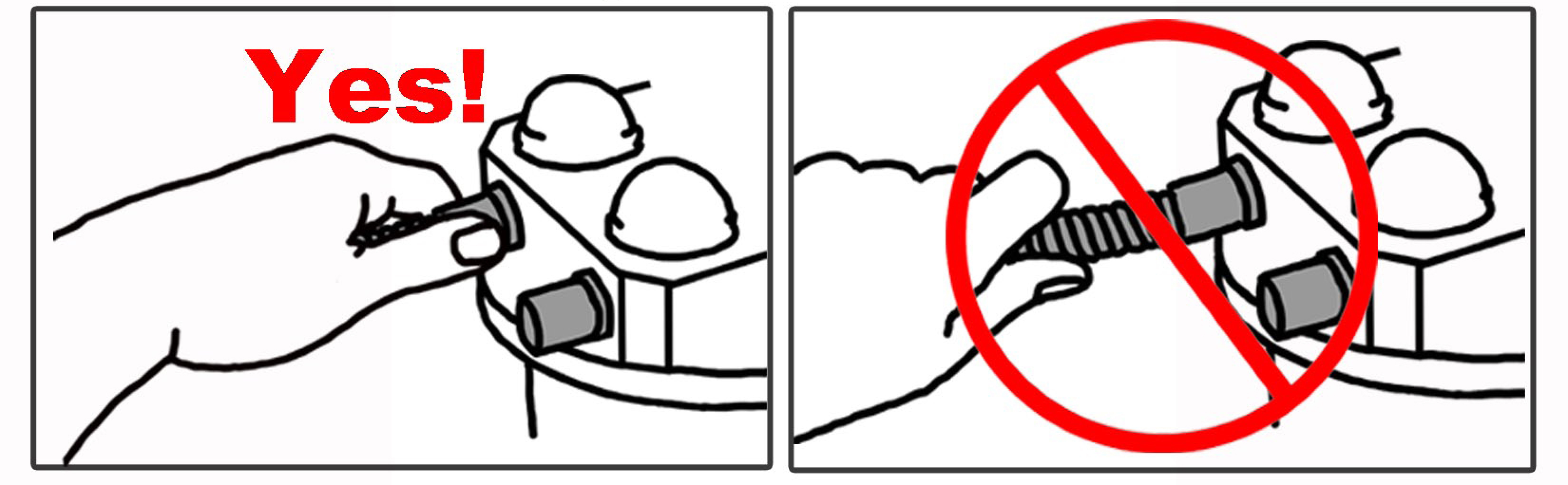
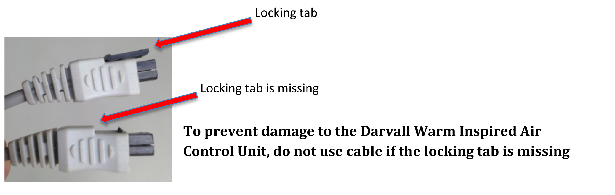 The 4-pin male connector on the Smooth Wall Heated Tubing Connection Cable (part#8615) connects to the female connector on the Heated SW Circuit (part#8347 or #8348). This connection MUST be aligned correctly to avoid damage to the Darvall Warm Inspired Air Control Unit.
If connected improperly, the computerized control board in the Darvall Warm Inspired Air Control Unit may be damaged and its warranty will be void. For complete instructions on connecting them properly, click here.
Collar Colors
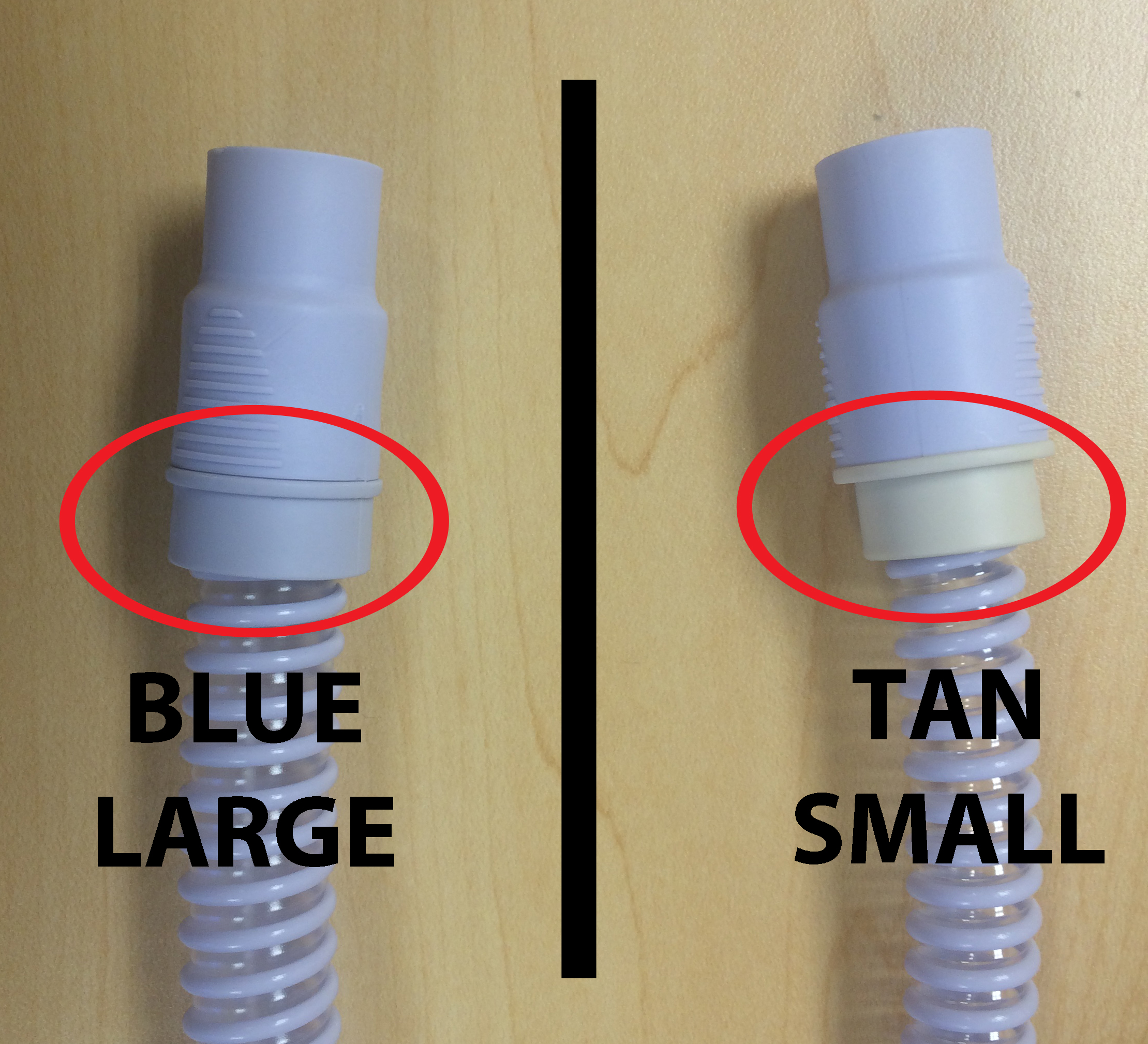
Darvall Smooth Wall (SW) Breathing Circuits come in two sizes: LARGE and SMALL. Large is for animals weighing over 45# and the collar color is blue. SMALL is for animals weighing under 45# and the collar color is tan.
Orange to Inspiration
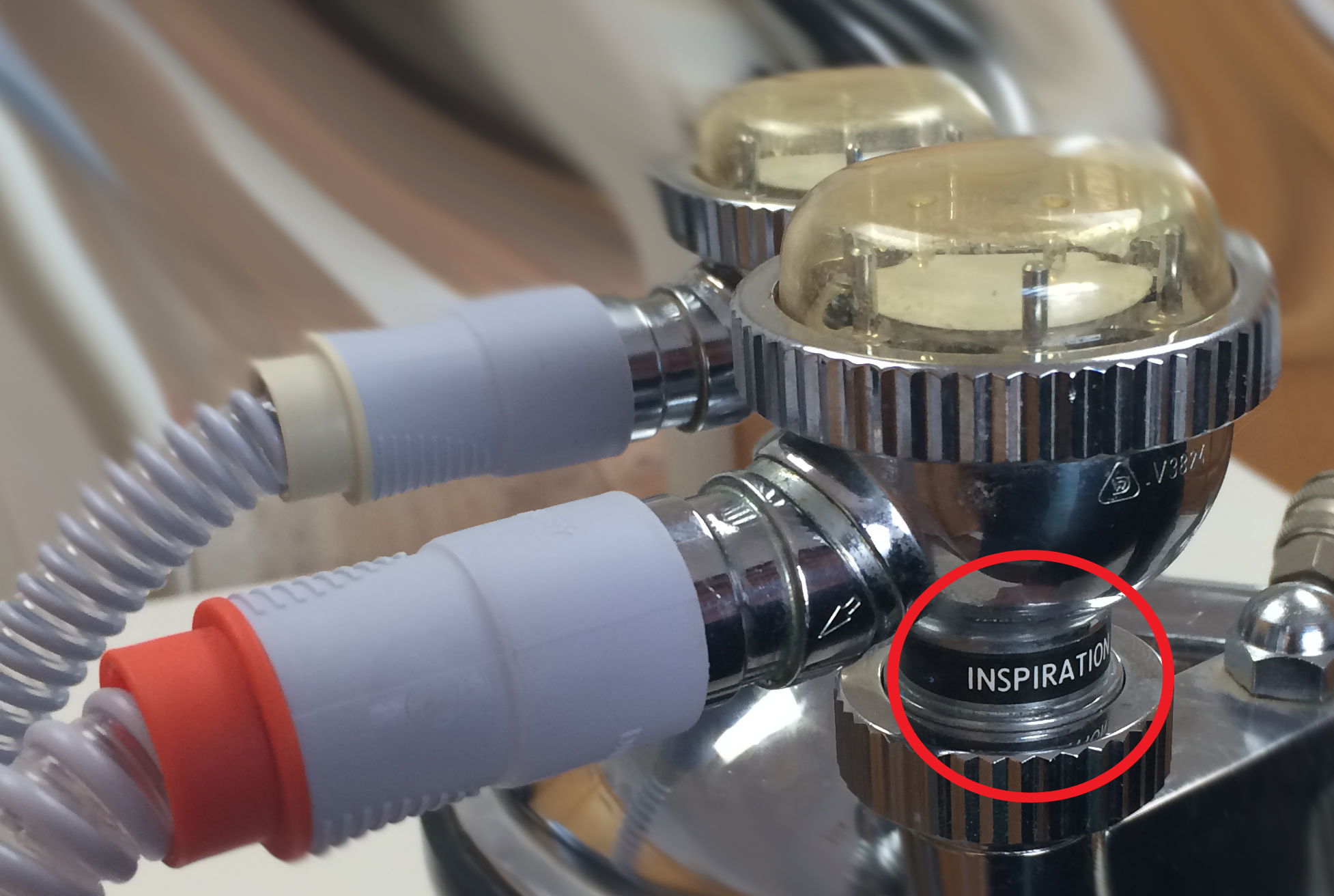
– click to enlarge –
In order to deliver warm inspired air to an anesthetized animal, the tubing with the orange collar must be connected to the inspiration side of the circle system.
Oxygen Flow Rate Is Important

Darvall Smooth Wall (SW) Breathing Circuits are designed to warm inspired gases at lower oxygen flow rates. At higher oxygen flow rates the gases move too quickly through the tubing to allow sufficient warming. The suggested oxygen flow rate for Darvall Smooth Wall (SW) Breathing Circuits is 30ml/kg/minute. For more information about oxygen flow rates and circle systems, read Go With The Flow – How to decide the oxygen flow rate for small animal anesthesia.
When Removing Hoses